
This is the third in a series of notes developing a design for my next boat. Other notes can be found here. In the previous notes I discussed a series of potential hull build techniques, including tortured (or 'developed') ply. This note outlines a potential structure and build technique in tortured ply. This build has not yet been attempted and may never be, so don't take this as a recipe - it's a discussion document.
A 'gunwhale clamp' is constructed out of shuttering ply. This is a scarfed together 'table' of shuttering ply about 20mm thick, the full length of the boat, with a slot cut in it the shape of the desired plan of the upper edge of the tortured hull. The gunwhale clamp is braced to keep it in plane. Trestles are built to support the gunwhale clamp 1 metre off the build floor.
A panel of cheap but stable material, probably exterior ply, is scarfed together to 1220 x 9360mm and the hull side pattern lofted on to it from the half-scale model. The master pattern is cut out of this.
 Cutting and assembling the lower hull
Two panels of hull skin panel are scarfed together to 1220 x 9360mm and the master pattern is traced onto each. The hull sides are cut out. An inner stem piece is prepared and shaped.
Positions for the upper edge of the keel fillet, and for the stringers, are lofted onto the hull sides and clearly marked. It's possible that it would be a good idea to assemble the stringers to the sides at this stage, but my preference is not to do so as they will make glassing the inside of the hull much more difficult.
The hull sides are stitched together along the keel line, and are stitched to the inner stem piece. They are propped apart a pre-determined distance established fron the half scale model. A 100mm wide strip of woven glass is laid along the keel line and wet out with epoxy. 'Peanut butter' consistency epoxy is then trowelled in along the keel line up to marked line for the upper edge of the keel fillet. The top surface of the filled is faired horizontal, and the epoxy allowed to cure. The sides are not epoxied to the inner stem at this stage.
When the epoxy has cured, webbing straps with ratchet tensioners are fitted round the hull at 1 metre spacings, and gradually tensioned. As the hull approaches the desired shape is it lifted onto the clamp and, as the straps are further tightened, pushed down into it. When free edges of the hull sides are 50mm above the clamp, the straps are released, and removed by pushing temporary wedges between the skin and the clamp. The wedges are then removed. The hull is now assessed for fairness; if it isn't satisfactory it is scrapped at this stage.
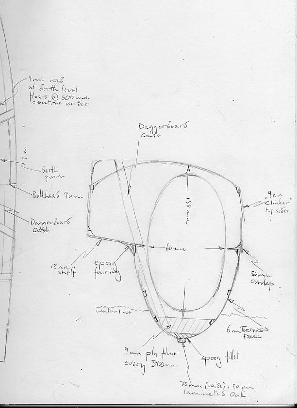
A gunwhale of 12mm x 50mm ash is fitted with its upper edge 9mm below the free edge of the panel, on the outer side of each hull, and level with the panel on the inner side of each hull. The transom, and bulkheads at the aft end of the coachroof and at the aft end of the bunk, are spiled and laid aside. The inside of the hull is glassed with 200gsm woven glass; this is wet out, and, while the epoxy is wet, the bulkheads are fitted and the stringers are slid in from aft. During this wetout the inner stem is also epoxied to the hull sides and the transom is fitted. The epoxy is allowed to cure.
A 9mm thick x 100mm wide shelf is spiled and fitted with epoxy fillet to the inner side of the free edge of the outboard hull side (i.e. the starboard side of the starboard hull, and vice versa) above the gunwhale, the full length of the hull. The panel to form the floor of the 'punt' - the inboard extension of the hull at cockpit floor level - is scarfed, cut and fitted to the inner side of the hull. The upper panel edges should now be adequately braced.
Floors of 9mm ply are now spiled, flowcoated and fitted as follows: between the transom and the after bulkhead, every 500mm with their tops 600mm above the lowest point of the hull; between the after bulkhead and the bunk bulkhead, every 300mm with their tops 200mm above the lowest point of the hull; between the bunk bulkhead and the stem, every 500mm with their tops 600mm above the lowest point of the hull. The aft locker sole, of 9mm ply, is then spiled and fitted between the transom and the aft cabin bulkhead, resting on top of and assembled to the floors. A 150mm diameter hole is cut the sole above each bilge compartment to act as an inspection hatch.
 Daggerboard trunk
The daggerboard trunk is now assembled and allowed to cure. Once cured, the assembly is spiled into the hull, and holes are drilled through the bottom skin to indicate the position where the slot must later be cut. I haven't determined yet whether the trunk fits immediately abaft or immediately forward of the bunk bulkhead; this depends on centre of effort/centre of lateral rtesistance calculations I haven't done yet. However, the trunk will but up against one side ot the other of this bulkhead. The trunk is spoxied into position with substantial filleting to the skin and to the bulkhead.
A sole of 9mm plywood is spiled for the area of the hull between the aft cabin and the the bunk bulkheads, but before it is fitted it is cut lengthways in three, and the centre section set aside. This is because, with the close spaced floors in this section of the hull, it would not be practical to have separate inspection covers for each compartment, and this centre strip will be fitted loose to allow for inspection of the bilge. The other two pieces are flowcoated, epoxied to the floors and filletted to the skin. The curvature of the bilge should now be adequately supported for the full length of the hull, which should no longer be floppy. However, it will remain in the clamp through the next operations.
A sole similar to that for the aft compartment is prepared and assembled forward of the berth bulkhead, forming the berth floor and the sole of the forward sail locker. As with the aft compartment floor it is fitted with 150mm inspection ports for each bilge compartment.
 Topside extensions
A 9mm ply panel is scarfed together to 1220 x 9360mm and the four topside strakes for the hull are lofted onto it and cut out. The top of the outboard hull panel is lightly faired to the angle for the lower outboard strake, and the strake is assembled to the hull overlapping the lower hull panel by 50mm. It is epoxied to the lower hull panel, and with fillets to the bulkheads and the the inner stem. To hold it in place while the epoxy cures it may be temporarily screwed through into the gunwhale and the inner stem.
The equivalent strake on the inboard side of the hull is in two pieces. The first assembles to the inner stem and the bulkheads, and its lower edge rests on the outer edge of the punt floor, where it is filleted in place. The short after section, aft of the rear cabin bulkhead, is assembled in a manner analogous to the outboard strake. Once the epoxy on these strakes has cured their upper edges are faired and the upper strake each side is assembled and epoxied to them, the bulkheads, transom and stem piece, overlapping the lower strake by 25mm.
Why two strakes, when it would be quicker and simpler to fit only one? Entirely as a design conceit. Overlapping the lower strake onto the tortured panel is necessary in my opinion to get adequate mechanical strength in the join, inevitably giving one continuous visible step in the hull side. If the topside extensions were added in a single piece, the result would look somewhat wall sided, but inducing compound curvature in the panel would be extremely difficult. By breaking the visual effect with a second overlap, a visual feature is introduced which is reminiscent of traditional clinker boat, and, at the same time, by emphasising horizontal lines in the topsides, will help make the boat look longer and lower.
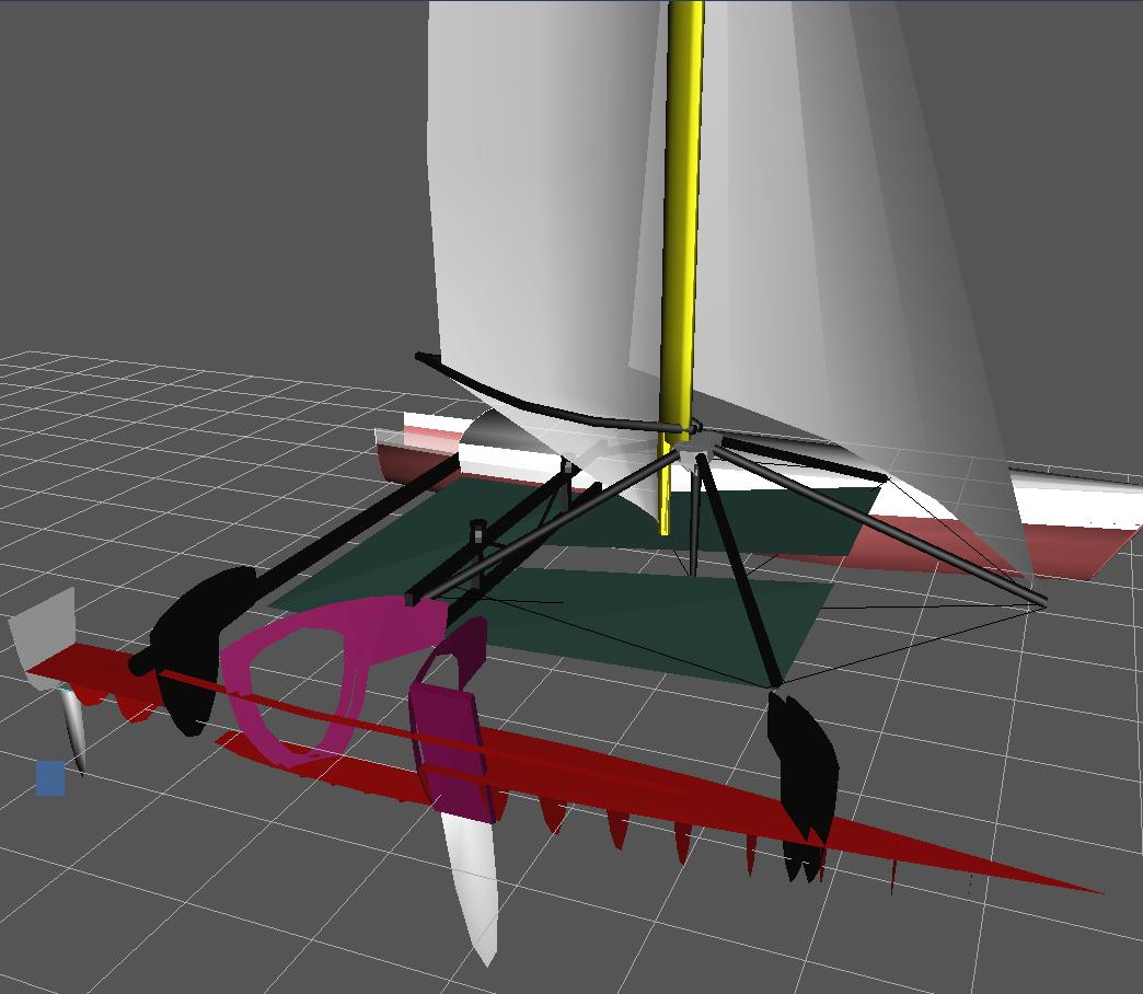
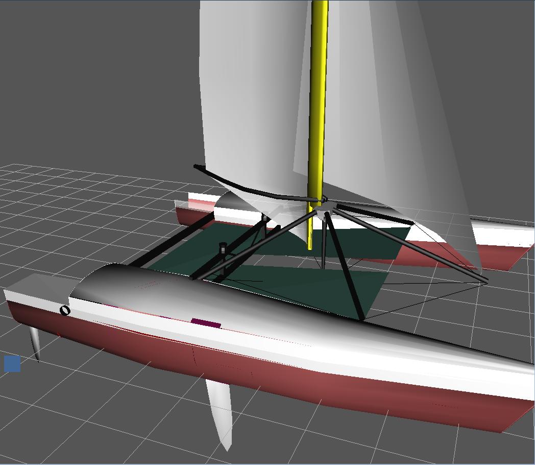
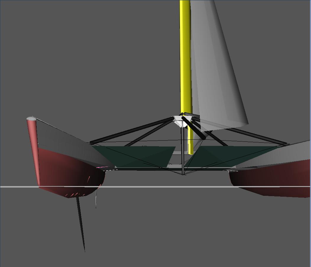
On a catamaran with conventional beams, the beams cross the hull at right angles and are conveniently supported by conventional thwartships bulkheads. My initial drawings for the stressframe cat also had conventional thwartships bulkheads, but clearly the boat will be stronger if the bulkheads which support the stress frame legs, and transfer the stresses between the hulls and the stressframe, are in line iwth the stress frame legs and consequently at decidedly odd angles to the hull.
I developed this idea with these as full bulkheads, but spiling and fitting these odd bulkheads into a still floppy hull just seemed too difficult, and I am at present thinking of fitting them as partial bulkheads after the floors and soles are in place and the hull is (hopefully) sufficiently rigid for someone to get inside.
Two bulkheads, each of 9mm ply, will be fitted at each stress-frame leg location, separated by the diameter of the stressframe leg. The leg itself will be bolted through reinforced lugs on the upper inboard end of these bulkheads protruding through the coachroof. Instead of extending down to the bottom of the hull as would be conventional, each bulkhead sits on the sole and is bonded and filleted to the sole, the skin, the punt floor and the topside strakes.
 The deck
The deck requires a degree of arch if there is to be even sitting headroom in the hulls. The arch isn't severe but it is greater than can be achieved with a plywood which would be strong enough unsupported to bear the loads of people walking about without considerable deflection. The deck also has to help in tying together the hull sides, which will inevitably have some residual tendency to spring apart.
I'm still undecided between three possible decking techniques. In the first, which I think at this moment I prefer, is to lay on a deck of thin - 3mm - plywood bonded to the bulkheads and upper strakes, then lay 12mm of core material - endgrain balsa or synthetic foam - onto that, and top with two or three layers of 200gsm woven glass cloth wet out and bonded with epoxy.
The second is to cut 12mm x 25mm hardwood stringers at 300mm spacings into the tops of the bulkheads, and lay a 6mm ply deck on that. That would be hard to paint and sore on the head, but simpler to make.
The third is to strip plank the deck in 15mm Western Red Cedar and finish with one layer of 200gsm glass inside and out. That would be reasonably simple to make (the inside could be glassed after the boat had been inverted, except in the forward compartments which would be very tricky) but relatively expensive compared to the hull cost.
In any case the coachroof and foredeck is now assembled to the upper strakes and bulkheads, and the companionway and forehatch cut out. The afterdeck - a comparatively simple plywood-on-stringers structure - is also fitted. The hulls is now removed from the clamp and inverted.
With the hull inverted the skin is trimmed flush with the inner stem and the outer stem, of durable hardwood, is glued onto the inner and faired. The hull is sheathed. The exact sheathing is something I'm still thinking about; the plywood for the tortured panels will inevitably be very thin - probably as little as 6mm - so protection against abrasion and penetration is vital. The sheathing material will be chosen to optimise this. Once teh hull has been sheathed a 75mm x 50mm keel/rubbing strip of laminated oak or iroko is laminated and epoxied down the centreline, and the daggerboard slot is cut.
give me feedback on this page // show other people's feedback on this page